In my last post, titled Verizon No Longer Concerned With Telephones Connected With Wires, I described an interview Ivan Seidenberg, chief executive of Verizon Communications, did at a Goldman Sachs investor conference on Thursday. In the inteview Seidenberg described how, by using the decentralized structure of the Internet rather than the traditional design of phone systems, Verizon had a new opportunity to cut costs sharply.
This summer I spent some time reading Martin Sauter's excellent new book Beyond 3G, Bringing Networks, Terminals and the Web Together. In the book Martin describes the movement in the wireless/cellular world away from circuit-switched telephony technologies like 2G, 2.5G (EDGE) and even 3G to 4G based technologies like LTE and WiMAX.
What does wireless technology have to do with copper wires? Like these wireless technologies, the Public Switched Telephone Network (PSTN) uses circuit-switched telephony technology designed around voice. Even DSL (a technology basically designed to extend the life of the copper wire based network by a few years) is a circuit-switched service - Internet based traffic goes to the Internet and voice traffic goes - you guessed it - right to the PSTN.
Circuit-switch based networks have made a lot of sense for the past 100 years or so. They work well for voice calls because by nature they are deterministic. If a circuit is available a connection is made. If a circuit is not available the call attempt gets rejected and the customer gets some kind of message back from the busy switch. Once a connection is made (phone-to-phone) the connection is also deterministic - each call is independent and cannot influence any other calls. A great design for voice communications - whether it be with copper wires or over wireless frequencies.
The problem with these circuit-switch based networks though is they were designed for voice. Sauter argues correctly that when networks are designed for specific applications, there is no separation between the network and the applications which ultimately prevents evolution. In addition, tight integration of applications and networks also prevents the evolution of an application because changing the applications also requires changes to the network itself. The PSTN basically cannot evolve beyond where it is now - it's been tweaked-up to the point where it cannot be tweaked-up any more.
Internet (TCP/IP based) technologies work using exactly the opposite approach. A neutral transport layer carries packets and any kind of application (voice, video, data, etc) can efficiently send high and low volumes of data through the network. For applications the connection process is transparent - the device operating system establishes an Internet connection before the application is even launched. The network and any applications running that use the network are independent of each other.
Verizon Wireless, AT&T, Sprint, etc are all moving to non-circuit-switched IP based 4G technologies like WiMAX and LTE to handle voice, video and data traffic. It is inevitable that Verizon's landline division (along with other landline carriers) move in this same direction.
Monday, September 21, 2009
Why the Public Switched Telephone Network Is Sunsetting
Monday, August 22, 2011
Telephone Set Function 2. To provide the telephone company with the number the caller wishes to call - Part 1
In this post I continue legacy Public Switched Telephone Network (PSTN) technology coverage.
There are two methods currently used to provide numbers to the telephone company, pulse or rotary dial service and dual tone multi frequency dialing. Let's look at pulse or rotary dial service in this post.
In the past, when a handset was lifted, the caller did not hear dialtone, the caller heard an operator asking for the number the caller wanted to dial. As the number of telephones grew, telephone companies projected that hundreds of thousands of new operators would be needed so rotary dials were added to telephones.


Tuesday, August 2, 2011
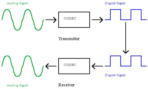
Analog to Digital (and Digital to Analog) with CODECs
In this post I continue to discuss the (rapidly disappearing) Public Switched Telephone Network (PSTN).
CODECs are used to convert analog signals to digital signals on one end and, on the other end, convert a digital signal back to an analog signal.

Thursday, November 24, 2011
Wavelength Division Multiplexing (WDM)
In my last legacy Public Switched Telephone Network (PSTN) post I covered Statistical Time Division Multiplexing (STDM). In this post let's take a look at Wavelength Division Multiplexing (WDM and DWDM) methods.
As bandwidth requirements continue to grow for both the legacy Public Switched Telephone Network and the emerged Internet/IP network most of the high bandwidth backbone transmission is being done with fiber optics and a method called Wavelength Division Multiplexing or WDM. WDM functions very similarly to Frequency Division Multiplexing (FDM). With FDM different frequencies represent different communications channels with transmission done on copper or microwaves. WDM uses wavelength instead of frequency to differentiate the different communications channels.


Tuesday, May 31, 2011
More Telephone History (1878-1918)
A couple of weeks ago I pulled a piece out of a book I wrote about ten years ago titled Introduction to Telecommunications Networks. In that post I described the first year in the development of telephone technology. As a follow-up to that post, here's some of the major technical breakthroughs that happened between 1878 and 1918.
1878
Bell sets up the first operator switching exchange and at the same time, Western Union Telegraph Company (http://www.westernunion.com) decided to use its existing national telegraph wire network to set up its own telephone company. Bell quickly sued Western Union and Western Union settled out of court, selling its network to Bell.
Henry Hummings in England gets a British patent for a variable resistance telephone transmitter that used finely ground carbon. The carbon transmitter solved many of the early problems Bell had trying to use liquid and electromagnetic transmitters. The carbon transmitter also used a voice cone attached to a diaphragm.

The diaphragm, which was attached to a conductor, vibrated with sound waves and caused the closed container of ground carbon to compress and uncompress changing resistance in the same way the liquid transmitters did.
1885
American Telephone and Telegraph Company (http://www.att.com) was formed to provide long distance telephone service, connecting small Bell regional telephone franchises.
AT&T buys Henry Hummings’ ground carbon variable resistance telephone transmitter patent rights.
1886
Thomas Edison modified Henry Hummings’ finely ground carbon transmitter by using larger carbon granules. The larger granules created more current paths with sound wave compression and therefore allowed more current to flow in conjunction with the compression. The larger granules also did not pack as tightly over time like the finely ground carbon in Hummings’ transmitter. When they did pack, usually lightly hitting the transmitter on a hard surface would loosen them up.
1899
AT&T reorganizes, assuming the business and property of American Bell and becomes the parent company of the Bell System.
1908
Siemens (http://www.siemens.com) first tests dialtone on the public switched telephone network in a German city.
1918
AT&T patents an anti-sidetone solution for telephone receiver and transmitters. This technology allowed talkers to more easily adjust their voice volume when speaking into the telephone transmitter.
I'll continue with more history in a later post.
Friday, August 12, 2011
The Basic Telephone Set Fundamental Functions
With my recent posts on the Public Switched Telephone Network (PSTN) I've been getting some email questions and suggested posts. I've received a few questions on telephones (what I would call end user devices) so I thought I'd take a few posts to describe how a basic telephone works.
The basic telephone set connected to the telephone network we are all very comfortable with using, has 4 basic functions:
- To provide a signal to the telephone company that a call is to be made (off-hook) or a call is complete (on-hook).
- To provide the telephone company with the number the caller wishes to call.
- To provide a way for the telephone company to indicate that a call is coming in or ringing.
- To convert voice frequencies to electrical signals that can be transmitted at the transmitter and convert those electrical signals back to voice frequencies at the receiver.

Saturday, November 17, 2012
Wireless and VoIP Services as Carrier of Last Resort?
The shift continues for the traditional telecommunications companies away from copper based voice and DSL data services to wireless and fiber. One of the road blocks that appears to be loosening are the Carrier of Last Resort (COLR) rules for carriers.
COLR rules are currently set at the state level (not the Federal Communications Commission) and regulate that every American has access to telephones service along with other utilities like electricity and water. A number of states have either passed legislation or are considering legislation that would end traditional landline rules and allow these services to be replaced by wireless (cell) or Voice over Internet Protocol (VoIP) services. Bills have emerged in Mississippi, Kentucky, New Jersey and California. Ohio's Senate Bill 271 is a good example of legislation currently being reviewed by lawmakers to cut traditional landline services.
... besides preserving social contact, land-line phones are needed to protect seniors' health and safety. For instance, some seniors use the phone line to transmit routine health information from equipment in their home to their doctor's office.They can make an evaluation of a person's heart and how's it working, of their lungs, etc. That information would be very difficult to transmit over a cell phone.
This means that almost all of the remaining wires, networks or even the obligation to offer services over those wires and networks are all removed -- as much of this infrastructure is classified as "telecommunications". The Public Switched Telephone Networks, the utility, would suddenly be reclassified as an information service. Sayonara any telco rules, regulations and oh yes, your rights. Your service breaks... tough. Prices go up and there's no direct competition -- too bad. Networks weren't upgraded -- so what. Net Neutrality? Neutered.
Wireless service is great when it works. Wireless as carrier of last resort - someday yes but not just yet. AT&T has opened a window and the FCC now has an opportunity to step up and put a logical transitional process in place.
Sunday, October 23, 2011
Multiplexing - A Brief Introduction
In this post I continue discussing some of the different legacy technologies used by the Public Switched Telephone Network (PSTN). Today let's take a quick look at what multiplexing is.
Before the invention of the telephone both Alexander Graham Bell and Thomas Edison were experimenting with ways to transmit more than one telegraph signal at a time over a single wire. They both realized this was a critical piece if any communications network was to grow in the number of users.

Friday, September 30, 2011
Telephone Set Function 4. To convert voice frequencies to electrical signals that can be transmitted
In my last few legacy Public Switched Telephone Network (PSTN) posts, I covered pulse or rotary dial service, dual tone multi frequency (DTMF) dialing service and what makes a telephone ring. In this post let's look at microphones and speakers.


Sunday, September 25, 2011
Telephone Set Function 3 - To provide a way for the telephone company to indicate that a call is coming in or ringing
In my last two legacy Public Switched Telephone Network (PSTN) posts I covered pulse or rotary dial service along with dual tone multi frequency (DTMF) dialing service. In this post let's look at what makes a telephone ring.

Thursday, July 7, 2011
Those Copper Wires Coming Into Your House - The Local Loop
It’s all going to be going away soon but, for most of us, our landline phones are still connected the way they were 80 years ago......
The analog Public Switched Telephone Network (PSTN) or Plain Old Telephone Service (POTS) local loop is defined as the twisted pair of copper wires many of us have coming into our home or business. This local loop is sometimes referred to as the “final three miles” or simply the “final mile”. The local loop has been “tuned” to our voice frequencies over the last 100 years and has a bandwidth of approximately 4000 Hz. This bandwidth includes two guardbands to prevent adjacent frequency interference. As can be seen in the figure below, bandwidth available to the local loop circuit for actual voice analog transmission is about 3000 Hz.

PSTN Bandwidth
The local loop wire pair consists of two wires and runs from a home or business to a Local Exchange Carrier (LEC) Central Office (CO) which is also referred to as the Central Exchange (CE). The CO provides voltage (– 48V DC) for the telephone in our homes and businesses. The wires that make up a wire pair are identified as follows: The “tip” (red wire) is attached to the negative side of the CO 48 V battery and the “ring” (green wire) is attached to the positive side of the CO 48 V battery.

Local Loop Telephone Circuit
This diagram shows a basic local loop telephone circuit. Notice the CO provides the voltage for the telephone. This voltage is provided by batteries in the CO – we’ve all experienced power failures at one time or another and most realize telephones still work even when the power is out. Also notice the battery polarity is inverted and a –48 V DC is being provided to the phone. This is done for electrolytic corrosion reasons. In my next post we’ll look at the local loop in the form of a transmission line.
Thursday, September 1, 2011
Telephone Set Function 2. To provide the telephone company with the number the caller wishes to call - Part 2
In my last legacy Public Switched Telephone Network (PSTN) post I covered pulse or rotary dial service. Let's look at dual tone multi frequency (DTMF) dialing service in this post.

Tuesday, May 17, 2011
The First Year Of The Telephone
About ten years ago I wrote a book titled Introduction to Telecommunications Networks. About half the book described how the now rapidly disappearing public switched telephone network (PSTN) worked. I haven't picked up the book in a while but a recent flip through has certainly brought back some memories. I thought it would be interesting to take a look at some of the history. Here's how it all started.
1876
Alexander Graham Bell and Elisha Gray, another inventor competing with Bell, are both scrambling to get their voice transmission inventions patented.
February 14, 1876
On this day Alexander Graham Bell’s father in law, attorney Gardiner Hubbard, delivered a patent application from Bell to the U.S. Patent for a device that transmits voice frequencies across wires.
Approximately three hours later on the same day Elisha Gray filed a caveat (a formal notice of an invention Gray hoped to patent) with the U.S. Patent Office describing a device that also transmitted voice frequencies across wires.
March 10, 1876
Alexander Graham Bell and Thomas A. Watson demonstrate a working telephone system but not without controversy. When Bell’s original patent and Gray’s caveat, both filed on February 14, were reviewed it was determined the device Bell described would not have worked while Gray’s would have. It was speculated that Bell had copied parts of Gray’s design. In Gray’s caveat he had detailed the use of a variable resistance transmitter which was used to produce a transmitter signal robust enough for the receiver to hear. Bell had been struggling to solve this same problem. In Bell’s patent application he made what appeared to be a last minute handwritten notation about the use of a variable resistance transmitter. People speculated that Bell had found out about Gray’s caveat and learned of Gray’s use of a variable resistance transmitter and, at the last minute before filing, Bell made a note on the patent application about using the new transmitter.
The variable resistance transmitter demonstrated by Bell on March 10, 1876 used a voice cone attached to a diaphragm. Also attached to the diaphragm was a wire that was emersed in a metal container of acidic solution.

The user talked into the voice cone, voice sound waves caused the diaphragm to vibrate and the wire moved up and down in the acidic solution. As the wire moved up and down in the solution the resistance between the wire and the metal container changed causing the DC current to vary in proportion to the variation in sound waves.
The controversy between Bell and Gray lead to years of litigation to the level of the United States Supreme Court where a split decision gave Bell the patent for the telephone entitled Improvements in Telegraphy.It took a little over a year for Bell to acquire and convince his wealthy father-in-law, Gardinar Hubbard, to finance the Bell Telephone Company and fund the building of the voice network infrastructure.
It's interesting to look back at the legal back and forth between Bell and Gray. It reminds me a lot of what we're seeing between Mark Zuckerberg and Facebook, the Winklevoss Twins, Wayne Chang, Paul Ceglia.... and others.
Friday, October 7, 2011
A Few Additional Telephone System Features
In this post I continue to describe the legacy Public Switched Telephone Network (PSTN), looking at a few other common telephone system features we are all used to having and relying on. These are additional handset signals and PIC. I would also want to include Caller ID here but I've already covered how it works in a previous post.
Tuesday, March 13, 2012
Synchronous Optical Network - SONET
In the United States T-1 carriers have been replaced in many locations with Synchronous Optical Network (SONET) systems. Internationally, the SONET equivalent is called Synchronous Digital Hierarchy (SDH). Both SONET and SDH systems consist of rings of fiber capable of carrying very high bit rates over long distances. Copper has been replaced by fiber to inter-connect most Central Offices (CO’s) in the United States at bit rates ranging from the SONET base rate of 51.84 Mbps up to 39,813,120 Gbps.


Saturday, March 10, 2007
Vonage and Verizon
Yesterday Vonage Holdings (2.2 million customers) was ordered by a federal jury in Alexandria to pay $58 million to Verizon Communications. The jury ruled that Vonage has infringed on Verizon patents by connecting the Vonage Internet based voice network to the Verizon Public Switched Telephone Network (PSTN).
There were actually three Verizon patents that the jury said we infringed upon by Vonage – the most significant one involves technology that links Internet voice with the PSTN. The two others involved call forwarding and wireless headsets.
In addition Verizon has asked the court to issue a permanent injunction that would stop Vonage from ever connecting to the PSTN. A permanent injunction would allow Vonage customers to only communicate with other Vonage customers using the Internet – something you can already do with many free services like Skype, Yahoo IM and Google Talk. There is a hearing scheduled for March 23 based on Verizon’s injunction request.
Last year the Supreme Court ruled to give judges in patent cases more latitude so the ruling comes as no surprise to both Vonage and Verizon. It will be interesting to see how this affects other providers offering similar domestic and long distance services.
Tuesday, October 25, 2011
Analog or Frequency Multiplexing
In this post I continue discussing some of the different legacy technologies used by the Public Switched Telephone Network (PSTN). Today let's take a dive into analog or frequency multiplexing.


This 240KHz is placed in the frequency range of 312 – 552 KHz.


This 2.40MHz is placed in the frequency range of 564 – 2.964 MHz.


This 14.4 MHz is placed in the frequency range of 3.084 – 17.484 MHz.

Frequency multiplexing is now considered obsolete technology on the telecommunications network. Analog signals are more sensitive to noise and other signals which can cause problems along the transmission path. Those long coaxial cables make pretty good antennas. They have been replaced with digital multiplexers. In my next legacy PSTN post I'll cover how digital multiplexing works.
Wednesday, November 21, 2007
Tera-bits Per Second Over Fiber
Tech.co.uk has reported that Tohoku University researchers in Japan have enabled Quadrature Amplitude Modulation (QAM) over fiber to move information at rates of hundreds of tera-bits per second. Here's a few quotes from the Tech.co.uk press release:
As the radio spectrum provides this, QAM-based methods work fine for some wireless protocols, however the nature of the optical spectrum means this has not been the case for fibre-optic cables ... until now.
The university team has solved the stability problem using a special laser that makes it feasible to pipe data down a glass fibre using the QAM method at blistering speeds. Although we shouldn't expect to be choosing from internet connections rated in Tbit/s anytime soon, the development could one day make us look back on ADSL as fondly as we now do our 56K modems.
Analog modems have used a form of QAM for years to move information from device to device across the Public Switched Telephone Network (PSTN) or voice network. QAM is also used by cable modems and ADSL modems to modulate (convert digital signals to analog) and demodulate (convert analog signals back to digital) communications signals.Let's try to get a basic understanding of how QAM works - without any math! Computing devices (computers, PDA's, laptops, etc) use digital signals (1's and 0's) to process, store and manipulate information. Sending this information over long distances though typically involves a conversion or modulation of digital signals to analog signals on the sending device and a conversion or demodulation of analog signals to digital signals on the receiving device. QAM has been the method of choice for transmitting signals this way for years.
QAM combines amplitude modulation (think height of a sine wave) and phase shift (think of a sine wave moving along the x-axis relative to a zero degree reference) and allows multiple bits (combinations of binary 1's and 0's) to be transmitted for each cycle of a sine wave. I like to use the term multiple bits per cycle when I describe QAM.
QAM is categorized by the number of bits that can be transmitted in one sine wave cycle. To get a simple understanding let's take a look at 16-QAM. 16-QAM is considered rectangular QAM - the square root of 16 is 4 and this indicates that each cycle of a 16-QAM waveform can represent a 4 bit binary (1 and 0) pattern. Using the same method we can calculate 64-QAM represents an 8 bit binary (1 and 0) pattern because the square root of 64 is 8. 256-QAM can represent a 16 bit binary (1 and 0) pattern because the square root of 256 is 16, etc.
QAM signals are susceptible to instability and noise but it appears the Tohoku University researchers have figured out a way to stabilize optical signals and use QAM methods for tera-bit level data transmission. I have not been able to find any detail on the stabilization methods being used at this time.
HAPPY THANKSGIVING!
Friday, November 11, 2011
Digital Multiplexing - Time Division Multiplexing


Thursday, October 20, 2011
The SLC-96
In this post I continue discussing some of the different legacy technologies used by the Public Switched Telephone Network (PSTN). Today let's take a look at how the PSTN designed and tuned for voice communications started to change in the late 1970's with something called an SLC-96 (pronounced "Slick 96").


